This is how the 4017 light chaster will look when you are done.
This is how the 4017 light chaster will look when you are done.
The next “Project of the Week” I was thinking about was a 4017 Light Chaser. I am thinking this because the first part of it is to build a 555, which we have already done, and the next part is to hook up a 4017 which is simple.
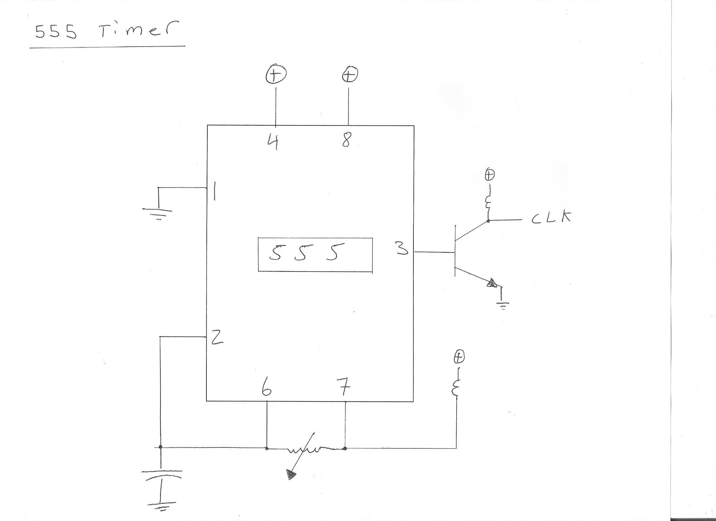
For those who know about electronics, this is what you can do when you hook up a darlington circuit (using NPN Transistors) to the output (pin 3). This is a 12 volt light bulb instead of an L.E.D.
I built the 555 timer myself and posted it on youtube a few months back. Here is the video for you so that you know what yours should look like.
You can use a 12 Volt, 1 Amp Ac Adapter if you have one. If not, use a nine volt battery and a battery clip. Here are the instructions.
1. Put the 555 I.C on the breadboard. Put it on so that the top left pin is in E3.
2. Put a green jumper wire from pin 1 of the 555 (B3) to the ground rail.
3. Put a 10 uF from the ground rail to pin 2 of the 555 (B4).
4. Put a red wire from pin 2 of the 555 (D4) to pin 6 of the 555 (G5).
5. Put a 1K resistor from pin 3 of the 555 (D5) to (B9).
6. Put a red wire from pin 4 of the 555 (D6) to the power rail.
7. Put the potentiometer from pin 6 of the 555 (G5) to pin 7 of the 555 (G6).
8. Put a 1K resistor from pin 7 of the 555 (H4) to the power rail.
9. Put a red wire from pin 8 of the 555 (G3) to the power rail.
10. Put a transistor in the output pins E (C10) ,B (C9) ,C (C8). When you put the transistor in, the flat side should be facing you.
11. Put a green jumper wire from pin E of the transistor (B3) to the ground rail.
12. Put a 1K resistor from pin C of the transistor (A8) to the power rail.
13. Put a 330 ohm resistor from pin C of the transistor (D8) to the output pin F10.
14. Put a green jumper wire from the output pin J11 to the ground rail.
15. Put the long leg of the L.E.D into H10 and the shorter leg into H11
16. Put the nine volt battery into the battery clip. The light should be flashing.
Here is the schematic for the 555 circuit.
Before you can build a 555, you will need to know some basic “Schematic Symbols”. A schematic is a technical drawing that tells the engineer how to build a circuit. A schematic is like a blueprint, without it, there is no direction. Here are the basic symbols you will need to know to build the 555 Timer. 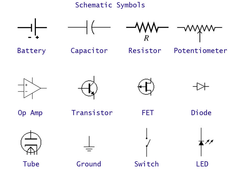
This is a resistor color code chart. This was the one I used at the beginning until I memorized it.
For example a Brown, Black, Red and gold is a 1K resistor with a 5% tolerance

Here is the list of parts you will need to build the 555 circuit. The number in the brackets indicate the quantity.
A 555 timer is one of the easiest and one of the most important circuits you will learn in circuitry.
That’s why this weeks “Project of the Week” is a simple 555 Timer circuit. Over the next 6 pages, I will show you how to build it step by step.
